The ASUS X99-E-10G WS Motherboard Review: 10GBase-T Networking with Intel’s X550-AT2
by Ian Cutress on November 7, 2016 9:00 AM EST- Posted in
- Motherboards
- Intel
- Asus
- 10G Ethernet
- X99
- 10GBase-T
- X99-E-10G WS
- X550
- X550-AT2
Board Features
ASUS is promoting the X99-E-10G WS as their highest-end SKU for X99 platforms. As a result, it costs a fair bit, given that the 10G controller and dual PCIe switches are not cheap individually, let alone a set.
| ASUS X99-E-10G WS | |
| Warranty Period | 3 Years |
| Product Page | Link |
| Price | US |
| Size | CEB (12 in x 10.5 in, 30.5 cm x 26.7 cm) |
| CPU Interface | LGA2011-3 |
| Chipset | Intel X99 |
| Memory Slots | Eight DDR4 DIMM slots supporting up to 128 GB Up to Quad Channel, 2133-3333 MHz (Xeon) Support for 128GB DDR4-2400 ECC Un-buffered (Xeon) Support for 128GB DDR4-2400 ECC RDIMM |
| Video Outputs | None |
| Network Connectivity | 2 x 10GBase-T (Intel X550-AT2) |
| Onboard Audio | Realtek ALC1150 |
| Expansion Slots | 7 x PCIe x16 (up to x16/x8/x8/x8/x8/x8/x8) via PLX8747 Support NVIDIA 4-way SLI Support AMD 4-way Crossfire Support 7-way Crazy OpenCL Configs. Probably |
| Onboard Storage | 6 x SATA 6 Gbps, RAID 0/1/5/10 4 x S_SATA 6 Gbps, no RAID 1 x U.2 (PCIe 3.0 x4) * switch with M.2 1 x M.2-2280 (PCIe 3.0 x4) * switch with U.2 |
| USB 3.0 / USB 3.1 | 1 x USB 3.1-A via ASM1142 1 x USB 3.1-C via ASM1142 8 x USB 3.0 (4 x back panel, two headers) |
| Power Connectors | 1 x 24-pin ATX 2 x 8-pin 12V EPS for CPU 1 x 6-pin PCIe for VGA |
| Fan Headers | 1 x CPU (4-pin) 1 x CPU OPT (4-pin, for water cooling fans) 2 x CHA/SYS (4-pin) |
| IO Panel | 2 x 10GBase-T (Intel X550-AT2) 4 x USB 3.0 1 x USB 3.1 Type-A 1 x USB 3.1 Type-C Audio Jacks |
| Other Features | TPM Header EZ XMP Switch Front Panel Header DirectKey Header MemOK Button CPU Overvolt Header Power/Reset Buttons Clear CMOS Button SLI/CFX Light Switch USB BIOS Flashback Button COM Header High AMP Fan Header Temperature Sensor Header |
One of the interesting things to note is the storage, whereby due to the PCIe lane allocation the motherboard only has suffcient PCIe lanes for either the M.2 or the U.2 slot - users cannot have both enabled simultaneously. At this point of the ecosystem, this is perhaps not a limiting thing given the sole U.2 commercial drive is the Intel SSD 750, however as this is a workstation motherboard chances are that OEMs who use this board will have access to enterprise level U.2 drives as well. We will have to wait until the HEDT chipsets enable more PCIe lanes in order to get multi-PCIe native functionality.
In The Box
We get the following:
IO Shield
User Manual
Driver DVD
10 x SATA 6 Gbps cables
1 x COM Port Cable
1 x 2-way SLI Bridge
1 x 3-way SLI Bridge
1 x 4-way SLI Bridge
1 x Q-Connector
1 x 2-port USB 2.0 Module
1 x 80cm Extension Cable for RGB
With an expensive product comes an expensive box set – having a full array of SATA cables for an X99 motherboard is rare. The 2-port USB 2.0 addition is a good one, allowing users to install an OS via non-xHCI chipset based ports rather than controller based ports (which can sometimes be an issue when it comes to drivers on the OS installer).
Visual Inspection
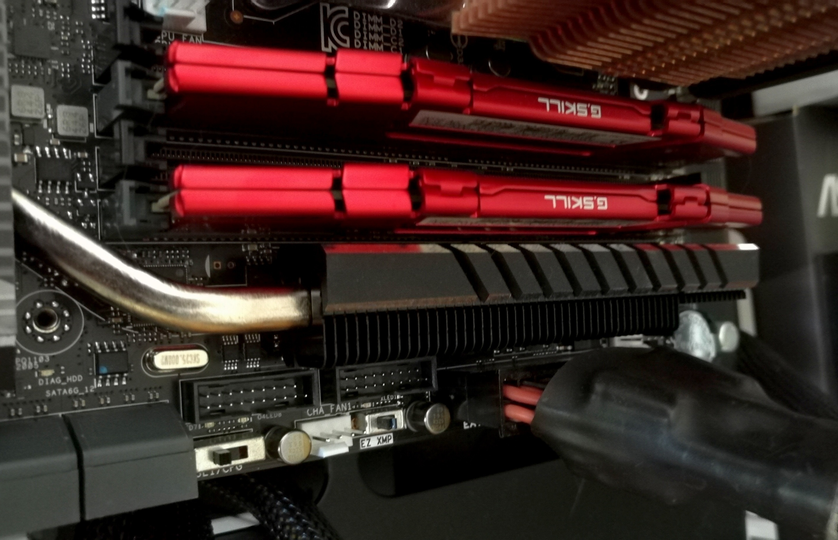
One of the things that it immediately noticeable on the X99-E-WS 10G as you pick it up is the weight. I wouldn’t be surprised if this is one of the heaviest motherboards we’ve ever tested, and this comes down to a large feature set which requires sufficient cooling. The addition of the X550-AT2 ten gigabit Ethernet controller for the network ports and the dual PLX8747 PCIe switches adds a peak 30W+ to the base chipset design and needs appropriate heatsinks as a result (ASUS recommends active cooling on the CPU to assist). This means that the typical power delivery and chipset heatsinks are extended and/or connected via heatpipes – one combination heatsink takes care of the power delivery and the Ethernet controller, while another does the PCIe switches and the chipset but also has an extension up the side of the DRAM slots to provide more mass and surface area for cooling.
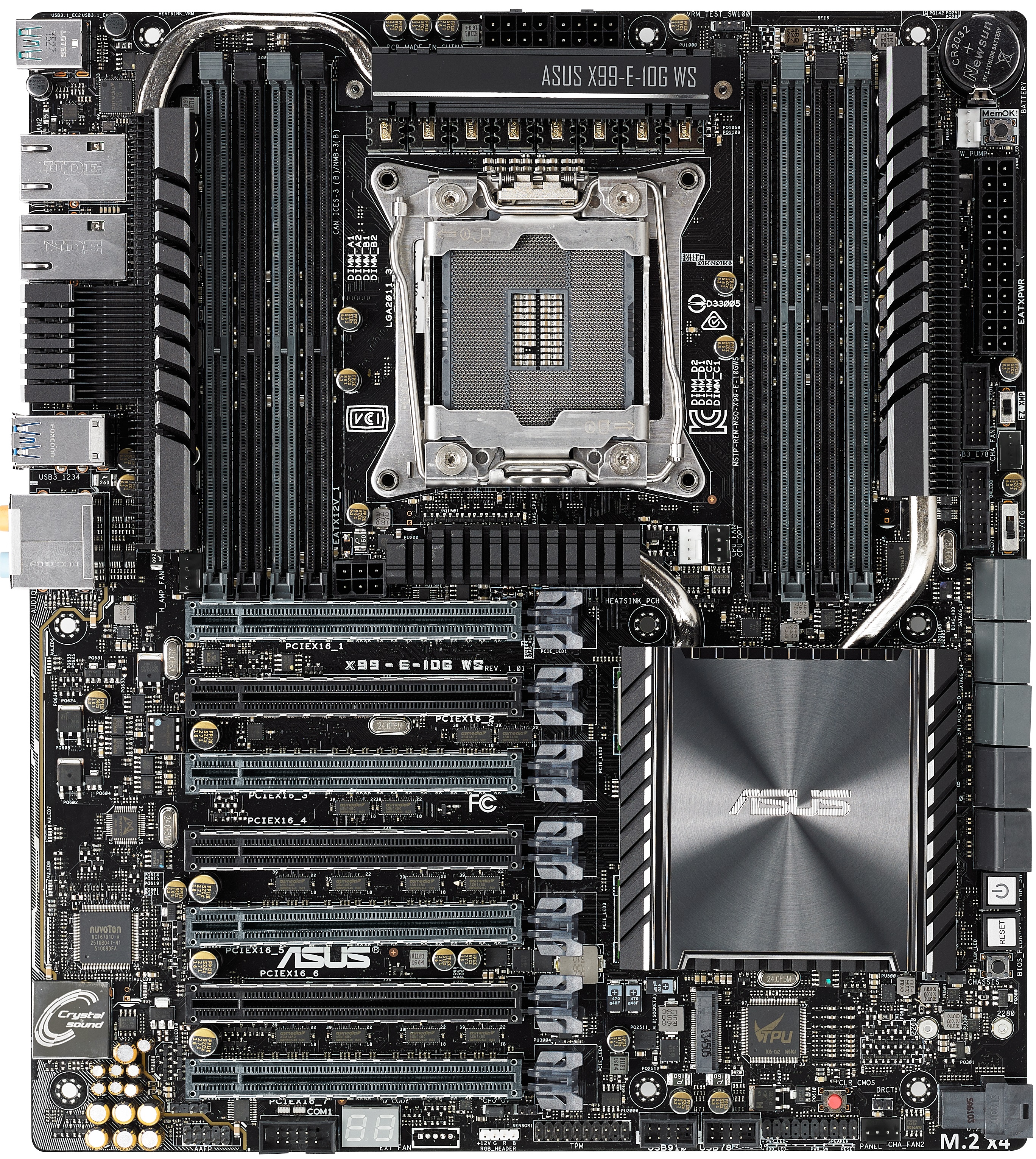
Mass and heatsinks aside, the socket area is where we typically start and despite this being a CEB sized motherboard, the socket is barely bigger than Intel’s minimum specifications as given by the white border in the socket area. Above the LGA2011-3 socket are eight power phases using premium chokes, which are supplied via dual 8-pin EPS 12V connectors (although only one is needed for stock use). The socket has five 4-pin fan headers for immediate use – two below the socket to the right (one white for the main CPU, one black for water cooling fans), one 4-pin to the far right next to the USB 3.0 headers, one in the top right for water cooling pumps, and a fifth 4-pin to the left of the socket just above the first PCIe slot. This fifth header is listed as a high-amp fan header, thus any enthusiast who wants to invest in a powerful or high static pressure fan can use this header. The final 4-pin fan header is at the bottom of the board. It is worth nothing that while there is a pad at the bottom of the board for ASUS’ fan extension board we’ve seen in other products, it seems to be removed for this version.
Moving clockwise around the motherboard, the DRAM slots are next. ASUS uses single-sided latch DDR4 slots, with the single-sided latch making it easier to change memory with a large GPU installed but users will have to make sure that memory is firmly pushed into place for connectivity. The DRAM slots use alternating colors to indicate the primary and secondary memory slots for the four channel design – in this case the grey slots are the primary memory slots and should be filled first.
At the top right of the board is the CR2032 battery, which is a particularly odd place for the battery that keeps the internal clock and BIOS operational (normally we see the battery nearer the BIOS chip and by the chipset, but as it requires to be ‘open’ for replacement and this board has little space, it looks like this is the only place ASUS could put it). Beneath the 24-pin ATX connector are two USB 3.0 headers powered by the PCH, and two DIP switches. The top switch is an EZ XMP switch, allowing users for most XMP enabled memory to apply the extreme profile without altering the BIOS. Tools like this are designed to work most of the time with the majority of kits, however with obscure or super-high performance memory your mileage may vary (users should not mix and match kits/speeds either). The second switch is labeled as SLI/CFG which is used to light up the various PCIe latches with where GPUs should be installed for the best performance in 2-way, 3-way and 4-way SLI. For seasoned enthusiasts, knowing which are the best slots should be second nature, but ASUS has received feedback that sometimes working it out is a bit complicated, hence this switch with visual feedback via LEDs.
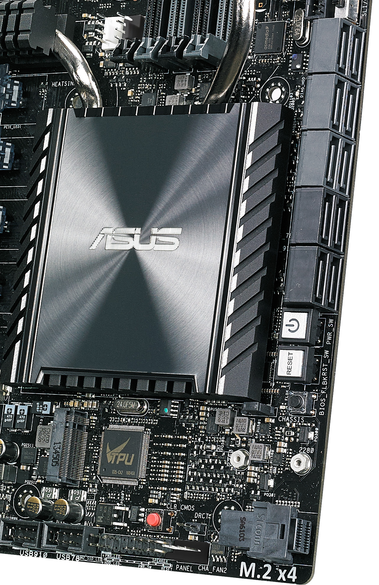
Beneath the switches are our SATA ports, with the X99-E-WS 10G implementing all ten from the chipset. The first six in light gray are from the primary SATA controller, and allow for RAID, while the other four in dark gray will not. For storage ASUS also has an M.2 PCIe 3.0 x4 slot further down for 2280 drives and a U.2 connector for drives like Intel’s SSD 750. Even when using a 40 lane PCIe CPU, only one of these PCIe storage options will work at once. In between the U.2 and the SATA ports are our power/reset buttons, along with a BIOS Flashback button.
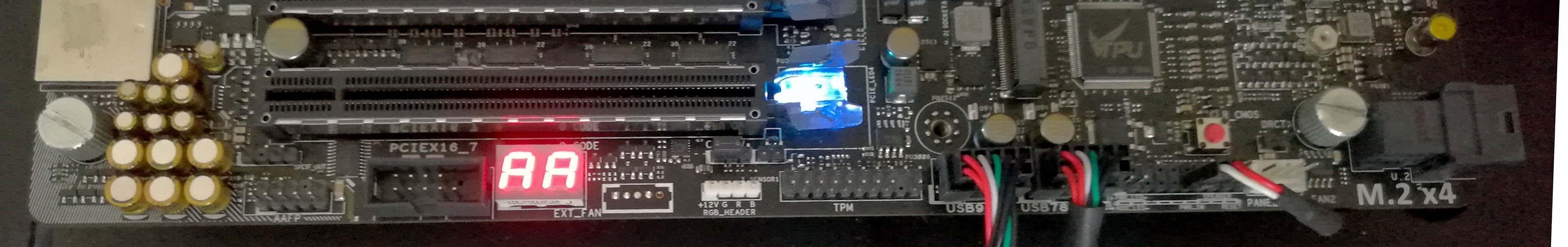
Moving to the bottom of the board and it gets very crowded. From right to left is the U.2 connector, one of the aforementioned 4-pin fan headers, above that is a DirectKey (reboot to BIOS) header, then a front panel header, and above this is a Clear CMOS button. Next are two USB 2.0 headers, a TPM header, and a header for an RGB LED strip (adjustable by using the OS software). Above the RGB header is a thermal temperature sensor header, for anyone with a two-pin thermistor who wants an additional thermal monitoring point in their system, and a CPU Overvolt jumper. This jumper allows an extreme overclocker, typically one using sub-zero cooling methods such as dry-ice or liquid nitrogen, to push the processor beyond the ‘safe’ limits imposed in the BIOS by ASUS. Finally, to the left of this jumper, is a two-digit debug LED, a COM header, and the front panel audio header.
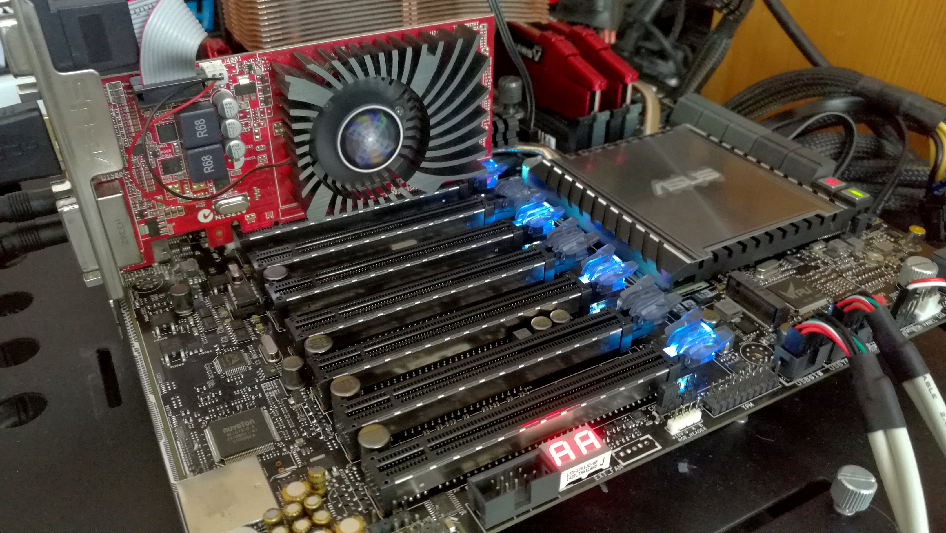
Moving to the PCIe slots, and we have an interesting discussion on our hands. Here are seven full-length PCIe slots, alternating in electrical connectivity as x16 and x8 respectively. Technically this motherboard will support PCIe 3.0 x16/x16/x16/x16 up to PCIe 3.0 x16/x8/x8/x8/x8/x8/x8, both of which are well beyond the 40 PCIe lanes provided by the CPU (and that’s not factoring in the PCIe storage or 10G Ethernet either). While not the best analogy, PCIe is almost like a freeway – some parts are wider than others but a 2-lane can become a 4-lane with an appropriate conversion. Same thing happens with PCIe using PCIe switches – using a PLX8747 IC, an 8-lane or 16-lane uplink can become a 32-lane to 80-lane downlink (depends on which version of the PLX IC, but each PLX IC has other features too, such as more device ‘ports’ for more hardware). So while communication on the downlink of the IC is up to 32-80 lanes, any devices on those lanes may compete for bandwidth in the x8/x16 uplink. We’ve covered the operation of PCIe switches many times before, with the original article back in 2012 (link), and ASUS uses similar techniques.
In order to get enough lanes in the right direction, ASUS does the following with the PCIe switches:
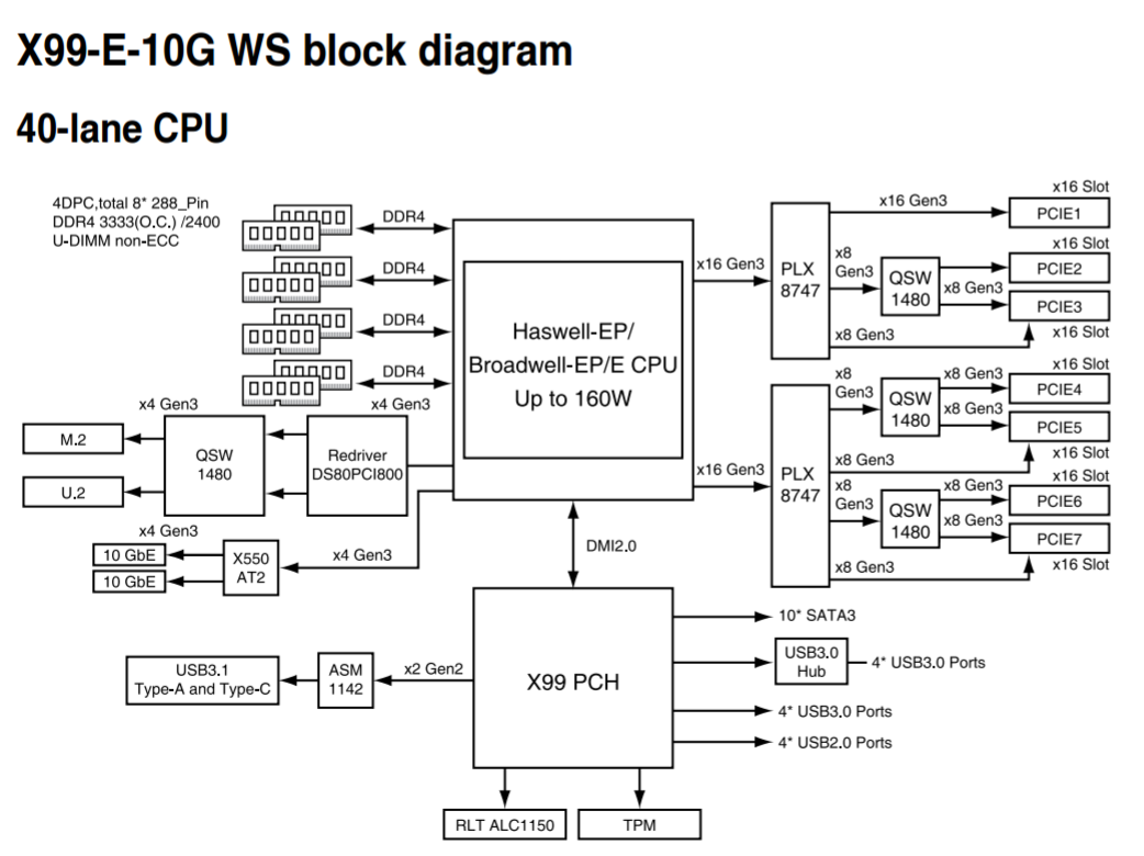
The 40 lanes from the CPU are split into three PEG (PCIe Graphics) links of x16, x16 and x8. The two x16 links are each fed into a PLX8747 which provides two x16 downlinks on each chip. Each downlink uses a quick-switch (QSW) to implement either a single slot x16 or dual x8 configuration. There are only seven slots on the board, so one of the downlink x16 stays at x16 (this is the top slot on the board). The final x8 from the CPU is split into two x4 links, one for the 10G controller providing the two ports of 10G and the other or PCIe storage at the bottom of the motherboard. All other PCIe related controllers (such as the ASMedia ASM1142 USB 3.1 controller) are derived from the chipset as it supports x1/x2 functionality.
Each PCIe slot on the board has embedded rigidity rails, which is a relatively new feature for high-end motherboards. The idea here is that PCIe devices, such as large GPUs, are often heavy due to the cooling causing the PCIe device to sag based on the weight. This puts the PCIe slot under stress and increased torque, and may increase failure rate (especially if the PCIe device is installed and then the system is shipped. While a user can invest in a frame to prop up the GPU, the motherboard manufacturers have taken the initiative and reinforced the slots themselves to reduce RMA rates (and offer another tick for marketing to promote/differentiate). The rails inside the plastic housing are also bonded to the PCB to ensure the PCIe slot doesn’t separate as easily under the increased stress.

The rest of the motherboard comes down to the audio and the rear panel. The audio implementation uses ASUS’ Crystal Sound branding, reserved for boards where an improved ALC1150 solution is needed but audio is not necessarily the focus of the board. This means we get PCB separation, additional filter caps for the front panel audio, an EM shield to reduce interference, and additional software. ASUS has historically been good at audio performance in our testing, and we see this again in the Crystal Voice design.
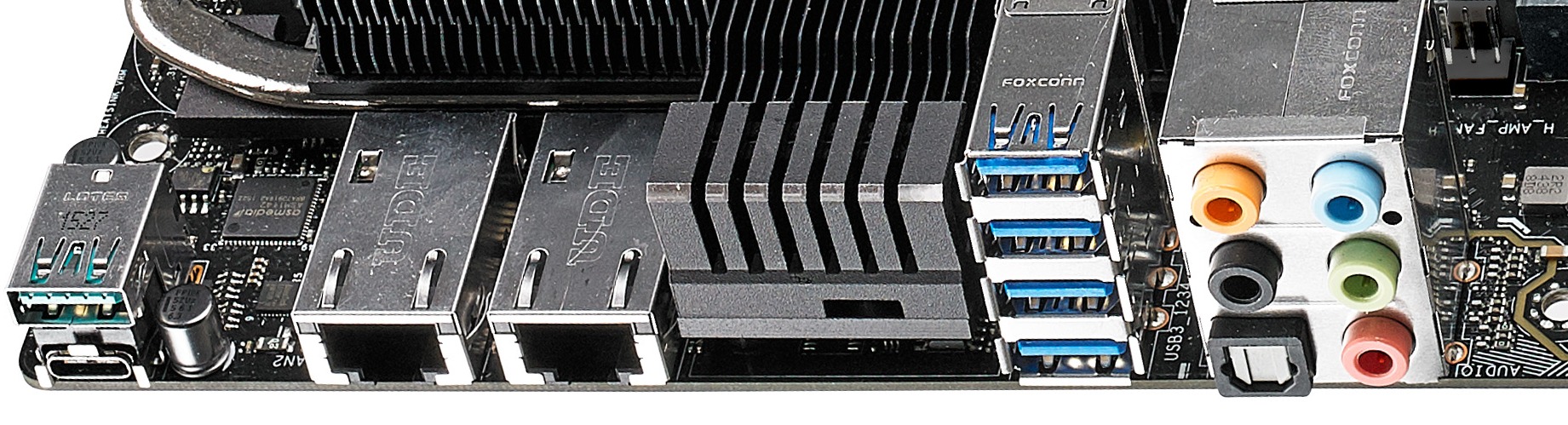
The rear panel starts with a pair of USB 3.1 ports from an ASMedia ASM1142 controller, and we get one Type-A and one Type-C. These can both take advantage of ASUS’ USB 3.1 boost technology, which we’ve tested for the benchmarking portion of the review. Following that are two 10GBase-T ports from the Intel X550-AT2 controller, which requires a section of the rear IO to be dedicated to heatsink as a result. It is worth noting that with all the current 10G implementations on consumer motherboards available, none of them put the 10G ports on top of one another, or pair with other ports on the same module. Next to the heatsink are the four USB 3.0 ports, followed by the audio jacks.
 Audio_thumb.png)
 Left_thumb.png)
 Top_thumb.jpg)
 Oblique_thumb.png)
 Rear IO 2_thumb.jpg)
 Rear IO_thumb.jpg)


63 Comments
View All Comments
maglito - Monday, November 7, 2016 - link
Article is missing references to XeonD with integrated 10Gbps networking in a much lower power envelope (Supermicro and ASRock Rack have great solutions). Also switches from Mikrotik ( CRS226-24G-2S+RM ) and Ubiquiti ( EdgeSwitch ES‑16‑XG ).dsumanik - Monday, November 7, 2016 - link
Fair enough, but one thing this article is NOT missing is better multi GPU testing, thank you Ian.In this day and age It is important to test every aspect of the board, not take the mfg's word for it or you wind up being a part of thier beta test.
Then when the bugs occur and sales slow, the bios team gets allocated to the more popular boards And you wait in limbo -sometimes permanently- for fixes
Gadgety - Monday, November 7, 2016 - link
I agree.prisonerX - Monday, November 7, 2016 - link
The XeonD has 10G MACs, which are not the particularly power hungry part of 10G ethernet, it's the PHY block, and in particular 10GBase-T which is the power hog. XeonD doesn't implement those.BillR - Tuesday, November 8, 2016 - link
Correct, the PHY is where the bulk of the power is used. I would expect the performance between the XeonD and the X550 to be similar since they use the same basic Ethernet MAC block logic. I would be a bit leery of using another LAN solution though, the Intel solution has been pretty rock solid. A problem I rarely have to think about is the best problem of all.ltcommanderdata - Monday, November 7, 2016 - link
You mentioned PCIe switches add a little bit of overhead which isn't a problem for graphics cards, but is the small added latency likely to be a concern for more sensitive applications like audio cards? Or is it better to use PCIe slots that are not on the PCIe switch for those?Also is there any sense yet on a time-to-market schedule for 2.5G/5G ethernet controllers and when motherboards and routers will start showing up with them?
TheinsanegamerN - Monday, November 7, 2016 - link
My guess is never. Outside of a very specific niche, nobody needs more then 1Gbps.JoeyJoJo123 - Monday, November 7, 2016 - link
>My guess is never, nobody needs HD. The human eye can't see past 640x480 interlaced.Eden-K121D - Monday, November 7, 2016 - link
nah 320X240 is the maxprisonerX - Monday, November 7, 2016 - link
640K should be enough for anyone.